SpeedFlow
- SpeedFlow 2.0 has been specially developed for the con- tinuous speed measurement of solids such as granules, powder and dust in metal pipelines.
- As the measurement is taken directly in the stream of material, the material can be measured during free fall or while being transported on pneumatic conveyors.
- The measurement is completely independent of the material itself.
- Its range of application starts at material speeds of 0.75 m/s.
Use
SpeedFlow 2.0 has been specially developed for the continuous
speed measurement of solids such as granules,
powder and dust in metal pipelines.
As the measurement is taken directly in the stream of
material, the material can be measured during free fall or
while being transported on pneumatic conveyors.
The measurement is completely independent of the
material itself.
Its range of application starts at material speeds of 0.75 m/s.
Function
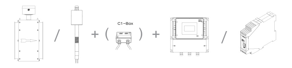
The complete measuring system consists of the following components:
- 1 x microwave particle sensor (reference sensor)
- 1 x microwave particle sensor (measuring sensor)
- C3-Box
- Transmitter in DIN Rail or field housing
- 2 x sensor socket for welding on the pipe
- Manual
System
A complete measuring point consists of the following components:
Pipe version:
Pipe version:
- Sensor in Jacob-pipe version:
DN 80 / 100 / 150 / 200 / 250 / 350 - Transmitter DIN rail or field housing
- Software
- Optional: C1-box
- Weld-on socket, including sealing plug
- Sensor with 2 m cable
- Transmitter DIN rail or field housing
- Software
- Optional: C1-box
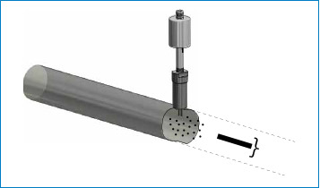
Mounting and installation
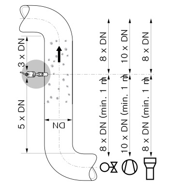
For mounting the sensor, the installation location is determined
according to the required inlet and outlet sections.
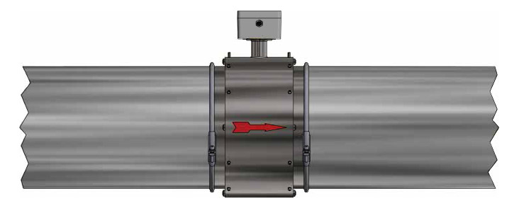
The SpeedFlow 2.0 sensor in the tube version comes with
a JACOBS tube connection and can be easily inserted
into an existing pipe system. Alternative adapters can be
purchased via ENVEA - SWR engineering.
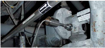
For the SpeedFlow 2.0 in the rod version, the weld-on socket is mounted at the specified installation location and a 20 mm borehole is drilled through the socket and through the pipe wall. Then the sensor is adapted to the wall thickness, inserted and fixed with the help of the union nut.
The distance between sensor and transmitter must not exceed 300 m. The connecting cable between the sensor and the evaluation unit should be four-wire, twisted in pairs and shielded.
Mounting and installation
Commissioning of the measurement takes place via an
transmitter in the field housing or DIN Rail housing. Both
evaluation units can be parameterized via software.
The PC software offers a input of parameters such as
measuring range, required physical units or measuring
signal attenuation. At the evaluation unit in the field
housing, the parameterization could be carried out additionally
without software on the touch display.
For signal output, a change-over relay contact, ModBus and a current output 4 ... 20 mA are available. The menu language (German, English or French) can be freely selected on the display as well as in the software.
For signal output, a change-over relay contact, ModBus and a current output 4 ... 20 mA are available. The menu language (German, English or French) can be freely selected on the display as well as in the software.
Technical Data
Sensor in pipe version
Transmitter (DIN Rail)
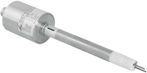
Sensor in rod version
Transmitter (field housing)
| Innerdiameter | DN: 80, 100, 150, 200, 250, 350 (other sizes on request) |
|---|---|
| Material inner pipe | PMMA |
| Mechanical connection | JACOBS flange |
| Protection category | IP 54 |
| Max. pressure | 100 mbar |
| Velocity range | 1…35 m/s |
| Temperature inside the pipe | 0…+50 °C |
| Temperatur outside the pipe | 0…+45 °C |
| Power supply | 24 V DC |
| Weight | Depend on diameter |
| Measuring accuracy | ± 1 % (in the calibrated measuring range) |
| Power supply | 24 V DC ± 10 % |
|---|---|
| Power consumption | 20 W / 24 VA |
| Protection type | IP 40 to EN 60 529 |
| Ambient operating temperature | -10 … +45 °C |
| Dimensions | 23 x 90 x 118 mm (W x H x D) |
| Weight | Approx. 172 g |
| DIN rail fastening | DIN 60715 TH35 |
| Connection terminals cable cross-section | 0.2 - 2.5 mm² [AWG 24-14] |
| Current output | 1 x 4 … 20 mA (0 … 20 mA), load < 500 Ω |
| Interface | RS 485 (ModBus RTU) / USB |
| Pulse output | Open Collector - max. 30 V, 20 mA |
| Relay contact | Max. rated load: 250 V AC Max. peak current: 6 A Max. rated load 230 V AC: 250 VA Max. breaking capacity DC1: 3/110/220 V: 3/0.35/0.2 A Min. switching load: 500 mW (10 V / 5 mA) |
| Data backup | Flash Memory |
| Weld-on socket | St52 or steel 1.4571 |
|---|---|
| Rod | Wolframcarbid |
| Housing | Steel 1.4571 |
| Protection category | IP 65 to EN 60529/10.91 |
| Rod length | 15 mm |
| Velocity range | 0.75…35 m/s |
| Temperature inside the pipe | -20…+80 °C (higher temperature on request) |
| Temperatur outside the pipe | 0…+60 °C |
| Power supply | 24 V DC |
| Weight | Approx. 1.5 kg |
| Dimensions | Ø 60, Ø 20, L 320 mm (incl. rod length) |
| Measuring accuracy | ± 1 % (in the calibrated measuring range) |
| Power supply | 110 / 230 V AC 50 Hz (optional 24 V DC) |
|---|---|
| Power consumption | 20 W / 24 VA |
| Protection type | IP 65 to EN 60 52910.91 |
| Ambient operating temperature | -10 … +45 °C |
| Dimensions | 258 x 237 x 174 mm (W x H x D) |
| Weight | Approx. 2.5 kg |
| Interface | RS 485 (ModBus RTU) / USB |
| Cable screw connectors | 3 x M20 (4.5 - 13 mm Ø) |
| Connection terminals cable cross-section | 0.2 - 2.5 mm² [AWG 24-14] |
| Current output | 3 x 4 … 20 mA (0 … 20 mA), load < 500 Ω |
| Pulse output | Open Collector - max. 30 V, 20 mA |
| Relay contact | Max. rated load: 250 V AC Max. peak current: 6 A Max. rated load 230 V AC: 250 VA Max. breaking capacity DC1: 3/110/220 V: 3/0.35/0.2 A Min. switching load: 500 mW (10 V / 5 mA) |
| Data backup | Flash Memory |